Blog
Electric Motor Safety Brake: What It Is, How It Works, and How to Choose the Right One
Author
Ray
Published
Category
Safety Brake for Rolling Door Motor
What is an electric motor safety brake? Discover how it works, key types, how to choose the right one, and maintenance best practices in this expert guide.

Author
Ray
An experienced automation specialist with a strong background in motor technology and industrial solutions. With years of expertise in central motors, tubular motors, and automation systems, the author is dedicated to sharing insights that connect engineering innovation with real-world applications. Passionate about advancing reliable, energy-efficient, and high-performance automation products for global markets.
What’s better than insider perks, pro tips, and surprises?
Sign up to get the most recent blog articles in your email every week.
Join now.
WHY I WRITE THIS
About my business
Our company’s main product lines include tubular motors, sliding gate motors, swing gate motors, roller shutter motors, and other door automation solutions, all manufactured by trusted partner factories we have worked with for many years.
Our Services
I help them with sales and export operations, while our company also provides sourcing and procurement services in China to help international clients solve supply-related challenges. If you need assistance with procurement, please feel free to contact us.
Introduction
If you've ever wondered what keeps an elevator from free-falling when the power goes out, or what stops a crane's load from crashing to the ground during an emergency shutdown, the answer is deceptively simple: an electric motor safety brake.
Despite being one of the most critical components in industrial machinery, the electric motor safety brake is often overlooked — until something goes wrong. In this comprehensive guide, we'll break down exactly what an electric motor safety brake is, how it works, the different types available, how to select the right one for your application, and how to maintain it for long-term reliability.
Whether you're a maintenance engineer, a machine designer, a plant manager, or a student entering the field, this guide will give you the practical, actionable knowledge you need.
What Is an Electric Motor Safety Brake?
An electric motor safety brake is a mechanical braking device integrated with or mounted onto an electric motor. Its primary purpose is to hold or stop the motor shaft — and therefore the connected load — when the motor is de-energized, during an emergency, or whenever a secure stopped position is required.
The Core Concept: "Fail-Safe"
The defining characteristic of a safety brake is its fail-safe design. Unlike a standard braking mechanism that requires power to engage, most electric motor safety brakes work on the opposite principle:
Power OFF → Brake ENGAGED (spring force clamps the brake)
Power ON → Brake RELEASED (electromagnetic coil overcomes the spring, allowing free rotation)
This means that in the event of a power failure, cable break, or control system malfunction, the brake automatically engages without any human intervention or electrical signal. The load is held securely in place.
In simple terms: A safety brake is your last line of defense against uncontrolled motion.
Why Are Motor Safety Brakes So Important?
The consequences of uncontrolled motor movement can range from equipment damage to catastrophic loss of life. Here are the primary reasons safety brakes are non-negotiable in many applications:
1. Personnel Safety
In applications like elevators, hoists, and robotic arms, an unbraked motor can result in falling loads, uncontrolled movement, or collision — all of which pose direct threats to human safety.
2. Load Holding
Vertical or inclined applications (cranes, lifts, conveyor systems on slopes) require the motor to hold position when stopped. Without a safety brake, gravity would cause the load to drift or fall.
3. Emergency Stopping
During an E-stop (emergency stop) event, all power is typically cut immediately. A fail-safe brake ensures the system comes to a controlled stop rather than coasting or free-wheeling.
4. Compliance with Safety Regulations
Many industries and jurisdictions legally require fail-safe braking on specific types of equipment. Non-compliance can result in fines, shutdowns, and liability exposure.
5. Equipment Protection
Uncontrolled motion can damage gearboxes, couplings, and downstream equipment. A safety brake protects your entire drivetrain investment.
How Does an Electric Motor Safety Brake Work?
Let's walk through the operating principle of the most common type — the spring-applied, electromagnetically released (SAER) brake.
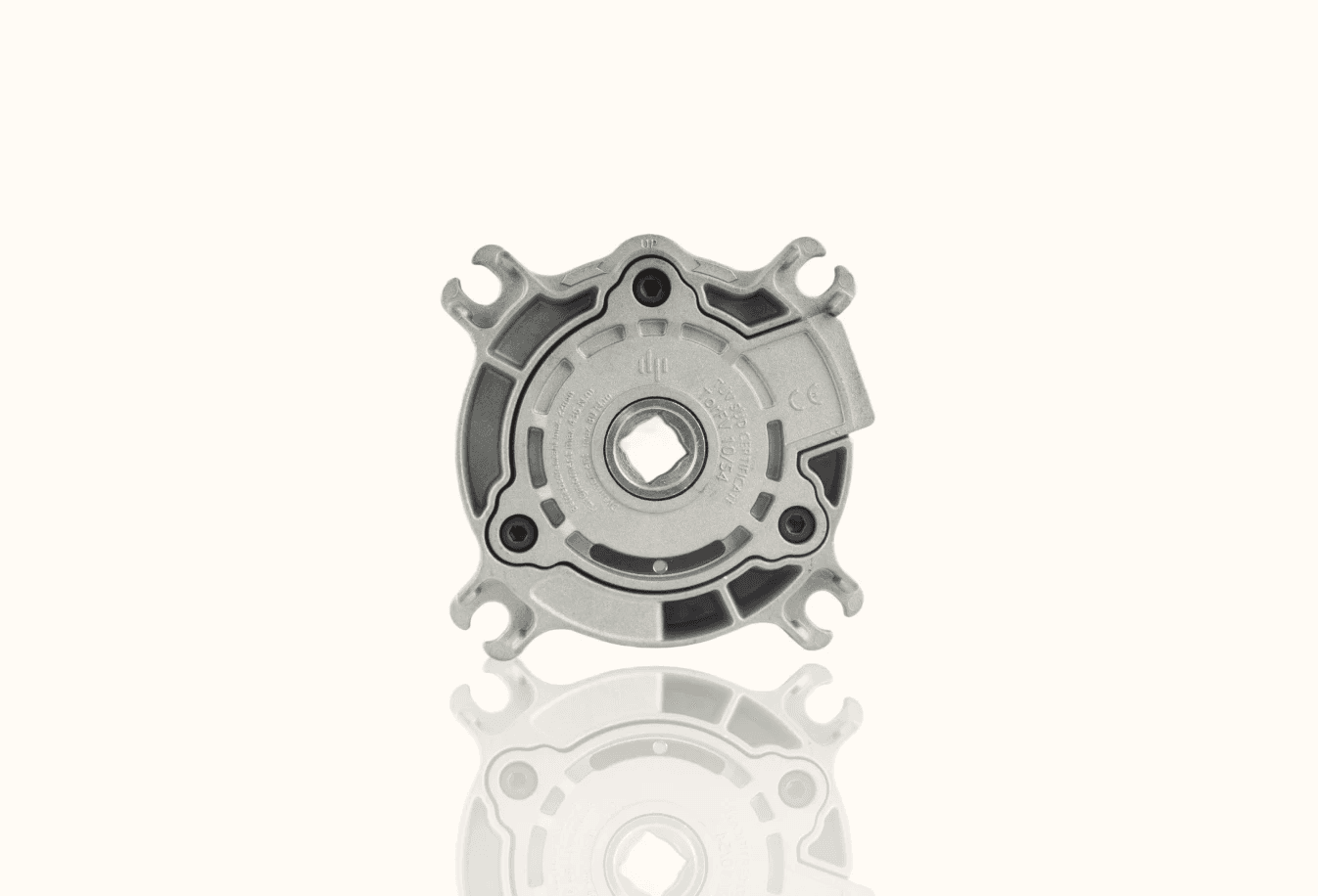
Components
Component | Function |
|---|---|
Brake disc (friction disc/rotor) | Mounted on the motor shaft; rotates with the shaft |
Pressure plate (armature plate) | Pressed against the brake disc to create friction |
Compression springs | Apply clamping force to the pressure plate when the brake is engaged |
Electromagnetic coil | When energized, creates a magnetic field that pulls the pressure plate away from the disc, releasing the brake |
Mounting flange/housing | Attaches the brake assembly to the motor frame |
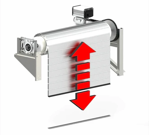
Operating Cycle
Step 1: Motor OFF — Brake Engaged
When the motor is not running (or power is lost), the electromagnetic coil is de-energized. The compression springs push the pressure plate firmly against the brake disc, clamping it between the pressure plate and the mounting surface. Friction prevents the shaft from rotating. The load is held.
Step 2: Motor Starting — Brake Released
When the motor is commanded to start, the control system first energizes the brake coil (typically DC voltage). The coil generates a magnetic field that attracts the pressure plate, compressing the springs and pulling the plate away from the disc. An air gap is created, and the shaft is free to rotate. The motor starts.
Step 3: Motor Stopping — Brake Re-engaged
When the motor is stopped, the coil is de-energized. The springs immediately push the pressure plate back against the disc. The shaft decelerates and is held in position.
Visual Summary
Braking Torque
The braking torque is determined by:
Spring force (number and strength of springs)
Friction coefficient of the disc material
Effective friction radius
Number of friction surfaces
The formula:
T = n × μ × F × R_eff
Where:
T = braking torque (Nm)
n = number of friction surfaces
μ = friction coefficient
F = total spring force (N)
R_eff = effective friction radius (m)
Types of Electric Motor Safety Brakes
Not all safety brakes are the same. The right type depends on your application requirements.
1. Spring-Applied Electromagnetic Brake (Most Common)
Mechanism: Springs engage; electromagnet releases
Fail-safe: Yes
Best for: General industrial use, hoists, cranes, conveyors, servo motors
Pros: Reliable, simple, proven technology
Cons: Friction disc wears over time; air gap requires periodic adjustment
2. Permanent Magnet Brake
Mechanism: Permanent magnets hold the brake engaged; electrical pulse releases
Fail-safe: Yes
Best for: Applications requiring very low power consumption, battery-operated systems
Pros: No continuous power draw; compact
Cons: More expensive; complex release mechanism
3. Spring-Applied Hydraulic Release Brake
Mechanism: Springs engage; hydraulic pressure releases
Fail-safe: Yes
Best for: Very high-torque applications (wind turbines, heavy mining equipment)
Pros: Extremely high braking torque; robust
Cons: Requires hydraulic system; more complex
4. Electrically Engaged Brake (Non-Fail-Safe)
Mechanism: Electromagnet engages the brake; springs release
Fail-safe: No — brake releases on power loss
Best for: Tension control, non-safety-critical positioning
Pros: Simple; inexpensive
Cons: Not suitable for safety applications — do not confuse with safety brakes
⚠️ Critical Distinction: Only spring-applied (fail-safe) brakes qualify as true "safety brakes." Electrically engaged brakes should never be used where holding a load or emergency stopping is required.
5. Multi-Disc Safety Brake
Mechanism: Multiple friction discs for higher torque in compact form
Fail-safe: Yes (spring-applied)
Best for: Servo motors, robotics, compact high-torque applications
Pros: High torque-to-size ratio
Cons: Higher cost; disc replacement more complex
Comparison Table
Type | Fail-Safe? | Torque Range | Complexity | Typical Cost | Common Use |
|---|---|---|---|---|---|
Spring-Applied Electromagnetic | ✅ Yes | Low–High | Low | $$ | Hoists, elevators, conveyors |
Permanent Magnet | ✅ Yes | Low–Medium | Medium | $$$ | Battery systems, AGVs |
Spring-Applied Hydraulic | ✅ Yes | Very High | High | $$$$ | Wind turbines, mining |
Electrically Engaged | ❌ No | Low–Medium | Low | $ | Tension control |
Multi-Disc | ✅ Yes | Medium–High | Medium | $$$ | Robotics, servos |
Key Applications Across Industries
Electric motor safety brakes are found in virtually every industry where motorized motion is present and safety is a concern.
Elevators and Lifts
Safety brakes are legally mandated on elevator drive motors. They must hold the fully loaded car in position during power failures and provide emergency stopping capability.
Cranes and Hoists
Every overhead crane, gantry crane, and hoist system uses safety brakes on the hoist motor (and often on travel motors). The brake must hold the rated load with a safety factor — typically 1.5× to 2× the maximum static load torque.
Wind Turbines
Large spring-applied hydraulic brakes are used on the main shaft and yaw drive of wind turbines. These brakes must withstand extreme environmental conditions and hold the rotor during maintenance or storm events.
Robotics and Servo Systems
Collaborative robots (cobots) and industrial robots use compact safety brakes on each axis. When the robot is powered down or an E-stop is triggered, the brakes hold each joint in position, preventing the arm from collapsing or swinging.
Conveyor Systems
Inclined conveyors carrying heavy materials (mining, aggregate, packaging) use safety brakes to prevent backward runaway when the motor stops.
Machine Tools (CNC)
Vertical axis (Z-axis) motors in CNC machines use safety brakes to hold the spindle head or workpiece in position when the machine is stopped.
Theater and Stage Equipment
Fly systems, automated scenery, and performer-flying rigs use safety brakes rated to SIL 3 or PLe standards, given the direct risk to performers and crew.
AGVs and AMRs (Automated Guided Vehicles / Autonomous Mobile Robots)
Safety brakes prevent uncontrolled rolling when the vehicle is parked, powered down, or in an emergency stop condition.
How to Choose the Right Safety Brake
Selecting the wrong brake can be just as dangerous as having no brake at all. Here's a systematic approach:
Step 1: Define the Application Requirements
Ask yourself these questions:
Is this a holding brake or a stopping brake?
Holding brake: Only needs to hold the load at standstill (motor decelerates the load; brake holds at zero speed)
Stopping brake: Must absorb kinetic energy and bring the load to a stop (much higher thermal demand)
What is the required braking torque?
Calculate the static torque needed to hold the load
Apply the appropriate safety factor (typically 1.5× for horizontal; 2.0× for vertical/lifting)
What is the duty cycle?
How many engagements per hour?
How much kinetic energy per stop?
What is the mounting configuration?
Shaft-mounted (C-face, IEC flange)?
Bolt-on to motor end bell?
Between motor and gearbox?
Step 2: Calculate Required Braking Torque
For a holding application (vertical load):
T_brake ≥ SF × T_load
Where:
T_load = (m × g × r) / (η × i)
m = mass of load (kg)
g = 9.81 m/s²
r = radius of drum/pulley (m)
η = gearbox efficiency
i = gear ratio
SF = safety factor (typically 1.5–2.0)
For a stopping (dynamic) application:
T_brake ≥ (J_total × ω) / t_stop + T_load
Where:
J_total = total moment of inertia reflected to brake shaft (kg·m²)
ω = angular velocity at time of braking (rad/s)
t_stop = required stopping time (s)
💡 Pro Tip: Always perform a thermal check for dynamic (stopping) brakes. The kinetic energy absorbed per stop must not exceed the brake's rated energy capacity. Repeated stops without adequate cooling will overheat and destroy the friction material.
Step 3: Check These Specifications
Specification | Why It Matters |
|---|---|
Rated torque (Nm) | Must exceed your calculated requirement |
Maximum speed (RPM) | Brake disc must be rated for your motor speed |
Coil voltage (VDC/VAC) | Must match your control system |
Response time (ms) | How quickly the brake engages after power cut |
Air gap range (mm) | Affects performance and maintenance interval |
Moment of inertia (kg·m²) | Adds to system inertia; important for servo applications |
Duty cycle rating | Engagements per hour; energy per hour |
Environmental rating (IP class) | IP54, IP65, etc. — must match your environment |
Operating temperature range | Critical for outdoor or high-heat environments |
Step 4: Consider the Environment
Dust and debris: Choose a sealed or enclosed design (IP65+)
Wet or washdown: Stainless steel or coated components; specialized friction materials
Explosive atmosphere: ATEX-certified brakes required
Extreme cold: Low-temperature grease; coil pre-heating
High temperature: High-temp friction material and coil insulation (Class H or higher)
Step 5: Verify Compliance
Ensure the brake meets the relevant safety standards for your application and region.
Installation Best Practices
Even the best brake will fail prematurely if improperly installed. Follow these guidelines:
1. Shaft Alignment
The brake disc must be properly aligned with the motor shaft. Misalignment causes uneven wear, vibration, and reduced braking torque. Use a dial indicator to verify runout is within the manufacturer's tolerance (typically < 0.05 mm).
2. Air Gap Setting
The air gap is the distance between the pressure plate and the brake disc when the brake is released. This must be set precisely according to the manufacturer's specification — usually between 0.2 mm and 0.5 mm for standard brakes.
Too small: Disc may drag, causing heat and premature wear
Too large: Coil may not generate enough force to release the brake; increased response time
3. Coil Wiring
Verify voltage and polarity
Use a brake rectifier if the control system supplies AC but the coil requires DC
Ensure proper wire gauge for the coil current
Include a suppression diode (flyback diode) or varistor across the coil to protect the control electronics from voltage spikes when the coil is de-energized
4. Mechanical Mounting
Torque all fasteners to specification
Use thread-locking compound where specified
Ensure the brake housing is rigidly mounted (no flex or vibration)
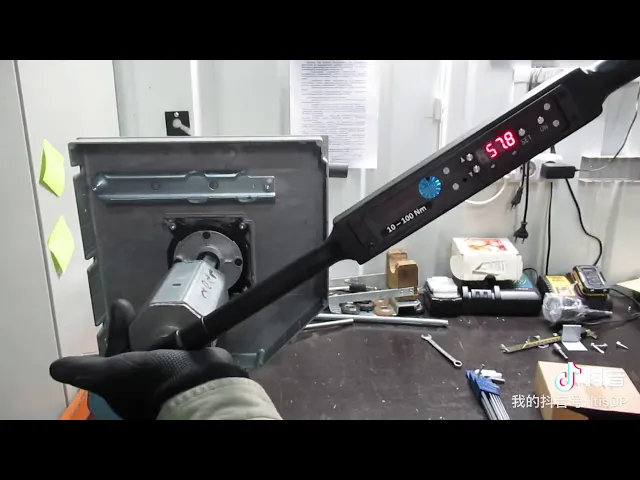
5. Functional Test
Before putting the system into service:
Verify the brake engages and releases properly
Measure the holding torque (use a torque wrench on the shaft)
Confirm response time meets application requirements
Test the fail-safe function by cutting power and verifying the brake engages
Maintenance and Inspection Guide
Regular maintenance is essential for reliability. A neglected brake is a dangerous brake.
Recommended Inspection Schedule
Interval | Inspection Item |
|---|---|
Daily | Listen for unusual noise; check for dragging |
Monthly | Visual inspection of disc wear, dust/debris, wiring |
Quarterly | Measure air gap; verify braking torque; check spring condition |
Annually | Full disassembly and inspection; replace friction disc if worn to limit; check coil resistance |
As needed | After any abnormal event (overload, E-stop under full speed, overheating) |
Key Maintenance Tasks
Air Gap Adjustment
As the friction disc wears, the air gap increases. Most brakes have an adjustment mechanism (manual or automatic):
Manual: Turn adjustment nuts or shims to restore proper air gap
Automatic: Some brakes have self-adjusting mechanisms (common in elevator brakes)
⚠️ Warning: An excessively worn disc with a large air gap may fail to release — the coil cannot pull the pressure plate across the larger gap. This will cause the motor to stall or the brake to burn.
Friction Disc Replacement
Replace the disc when:
Thickness reaches the manufacturer's minimum
Friction surface is glazed, cracked, or contaminated with oil
Braking torque has dropped below the required minimum
Coil Inspection
Measure coil resistance with a multimeter; compare to factory spec
Look for signs of overheating (discoloration, burnt insulation smell)
Check wiring connections for looseness or corrosion
Spring Inspection
Check for broken or weakened springs
Compare spring length to factory spec (springs lose force over time)
Replace springs as a complete set, never individually
Maintenance Log
Keep a detailed record of every inspection and maintenance action. This is not only good practice — it's often required by safety regulations and invaluable during incident investigations.
Common Failures and Troubleshooting
Problem 1: Brake Does Not Hold Load
Possible Causes:
Worn friction disc
Contaminated friction surface (oil, grease)
Broken or weakened springs
Excessive air gap
Incorrect brake sizing (undersized for the application)
Solution: Inspect disc condition; measure air gap; verify spring force; recalculate required torque.
Problem 2: Brake Does Not Release (Motor Stalls)
Possible Causes:
Coil failure (open circuit)
Incorrect or insufficient coil voltage
Excessive air gap (worn disc)
Mechanical binding (rust, corrosion, debris)
Solution: Check coil voltage at the brake terminals; measure coil resistance; inspect for mechanical obstruction; adjust air gap.
Problem 3: Brake Overheating
Possible Causes:
Brake used as a stopping brake beyond its thermal capacity
Too many engagements per hour (exceeding duty cycle)
Disc dragging (air gap too small or mechanical misalignment)
Incorrect application (using a holding brake for dynamic stopping)
Solution: Review application requirements; verify air gap; reduce cycle rate; consider upgrading to a higher-capacity brake.
Problem 4: Excessive Noise or Vibration
Possible Causes:
Disc runout (misalignment)
Worn or cracked disc
Loose mounting hardware
Damaged bearings (motor bearings, not the brake itself, but affecting alignment)
Solution: Check shaft runout; inspect disc; tighten mounting; inspect motor bearings.
Problem 5: Premature Disc Wear
Possible Causes:
Excessive dynamic stopping (high kinetic energy absorption)
Contamination
Misalignment causing uneven wear
Incorrect friction material for the application
Solution: Review application; correct alignment; select appropriate friction material; consider adding a separate dynamic braking system (resistor braking, regenerative braking) upstream of the safety brake.
Safety Standards and Compliance
Electric motor safety brakes are often part of a safety function as defined by international standards. Here are the key standards you should know:
ISO 13849 — Safety of Machinery
Defines Performance Levels (PL) from PLa to PLe. Safety brakes in machinery applications are often required to meet PLd or PLe. The brake itself is one component; the overall safety function includes sensors, control logic, and the brake.
IEC 62061 — Safety Integrity Levels (SIL)
Defines SIL 1 through SIL 3 for safety functions in machinery. Similar to ISO 13849 but uses a different methodology. Many brake manufacturers provide SIL ratings for their products.
EN 81-20/50 — Elevator Safety
Specific requirements for braking systems in elevators and lifts, including redundancy requirements (typically two independent braking circuits, each capable of holding the full load).
ASME B30 Series — Cranes and Hoists
Specifies braking requirements for various types of cranes and hoisting equipment in North America.
ISO 14120 / OSHA 1910.217
Various standards governing machine guarding and safety mechanisms in which braking systems play a role.
ATEX / IECEx
For brakes used in explosive atmospheres, certification to ATEX (EU) or IECEx (international) is required.
💡 Important: The brake manufacturer's datasheet should clearly state which standards the product complies with. Always request a Declaration of Conformity and, for safety-critical applications, the manufacturer's FMEA (Failure Mode and Effects Analysis) and B10d/MTTFd values needed for your safety function calculations.
Frequently Asked Questions (FAQ)
Q1: Can I use an electric motor safety brake as a stopping brake?
It depends. Most spring-applied electromagnetic brakes are designed primarily as holding brakes — they hold the load at standstill after the motor has decelerated the load. Using them for dynamic stopping (absorbing kinetic energy) is possible but requires careful thermal analysis. If your application requires frequent or high-energy stops, consider a dedicated dynamic braking system (e.g., regenerative braking, DC injection braking, or a separate dynamic brake) in combination with the safety holding brake.
Q2: How long does a brake disc last?
Disc life depends on the application. In a pure holding application with minimal dynamic engagement, a disc can last 5–10+ years. In a high-cycle dynamic stopping application, it may last only 6–12 months. Monitor wear through regular air gap measurements.
Q3: What happens if the brake engages at full motor speed?
The brake will attempt to stop the rotating shaft. This generates significant heat and wear. If the kinetic energy exceeds the brake's rated capacity, the friction material can overheat, glaze, or fail. This is an emergency scenario, not a normal operating condition. Design your control system to decelerate the motor before brake engagement whenever possible.
Q4: Can I adjust the braking torque?
On most standard spring-applied brakes, the torque is fixed by design (spring force and friction material). Some brakes offer torque adjustment by changing the number of active springs or adjusting spring preload. However, never reduce the torque below the minimum required for your application's safety function.
Q5: DC coil or AC coil — which is better?
Most modern safety brakes use DC coils, even when the power supply is AC (a rectifier converts AC to DC). DC coils provide:
Smoother engagement/disengagement
No humming or buzzing
Better control of response time
Longer coil life
AC coils are simpler (no rectifier needed) but can hum, generate more heat, and have less precise response characteristics.
Q6: What is the typical response time?
Engagement (power off → brake clamped): 15–50 ms for small brakes; up to 200+ ms for large brakes
Release (power on → brake open): 20–100 ms for small brakes; up to 300+ ms for large brakes
Response time is critical in safety calculations. Always use the manufacturer's tested values, not estimates.
Q7: Do I need redundancy?
For the highest safety levels (PLe / SIL 3), redundancy is typically required — two independent brakes, each capable of holding the full load. This is standard practice in elevators, personnel-carrying hoists, and stage/theater equipment.
Final Thoughts {#final-thoughts}
An electric motor safety brake is not a glamorous component. It doesn't make your machine faster, more efficient, or more productive. But when the power goes out, when the E-stop is hit, when something goes catastrophically wrong — it is the single component that stands between a safe outcome and a disaster.
Key Takeaways:
✅ Always use a fail-safe (spring-applied) brake for safety-critical applications — never an electrically engaged brake.
✅ Size the brake correctly. Undersizing is dangerous; oversizing wastes money and adds unnecessary inertia.
✅ Understand your application. A holding brake and a stopping brake are not the same thing.
✅ Maintain religiously. Air gap measurement and friction disc inspection are your most important maintenance tasks.
✅ Know your standards. ISO 13849, IEC 62061, and application-specific standards will tell you exactly what's required.
✅ Document everything. Maintenance logs, torque measurements, and inspection records are essential for safety compliance and liability protection.
The electric motor safety brake is a mature, well-understood technology — but only when properly selected, installed, and maintained. Cut corners here, and you're gambling with lives and equipment.
Other Blogs