Blog
Central Motor for Industrial Doors: What It Is, Parts, and How It Works
Author
Ray
Published
Category
Roller Shutter Motor
Learn what a central motor for industrial doors is, the key components (gearbox, brake, limit switch/encoder), and how the open/close cycle works.


Author
Ray
An experienced automation specialist with a strong background in motor technology and industrial solutions. With years of expertise in central motors, tubular motors, and automation systems, the author is dedicated to sharing insights that connect engineering innovation with real-world applications. Passionate about advancing reliable, energy-efficient, and high-performance automation products for global markets.
What’s better than insider perks, pro tips, and surprises?
Sign up to get the most recent blog articles in your email every week.
Join now.
WHY I WRITE THIS
About my business
Our company’s main product lines include tubular motors, sliding gate motors, swing gate motors, roller shutter motors, and other door automation solutions, all manufactured by trusted partner factories we have worked with for many years.
Our Services
I help them with sales and export operations, while our company also provides sourcing and procurement services in China to help international clients solve supply-related challenges. If you need assistance with procurement, please feel free to contact us.
A central motor for industrial doors—often described as a central drive operator or central shaft motor—is the powered drive unit that moves an industrial door by turning a central shaft/spindle or equivalent transmission point. It works as a system: the motor provides power, a gearbox and mechanical transmission deliver torque to the door, and the control system stops movement precisely using limit control (limit switch) and/or position feedback (encoder). During operation, it coordinates speed changes (deceleration), braking, and safety interlocks (including a safety edge connection) so the door opens/closes reliably without damaging equipment or endangering people.
Quick Answer: What a Central Motor Is (and what it does)
In practical terms, a central motor is the part of an industrial door motor system that:
Turns a drive shaft / spindle connected to the door mechanism (commonly a roll-up style or rolling mechanism, depending on door design).
Uses gearbox / geared motor architecture to deliver the torque needed for the door’s weight and friction.
Uses a braking system (often a motor brake) to stop and hold the door safely at end positions.
Uses a controller (control board / control unit) plus feedback devices (limit switch and/or encoder) to precisely manage the open/close sequence.
Central motor vs end/side drive (simple positioning idea)
You’ll often hear “central,” “end,” and “side” drives used in industrial door discussions:
Central drive: power comes from the middle drive point (shaft/spindle) and transmits motion through the door mechanism.
End/side drive: power is applied from an end or side, usually changing how force is delivered and how the door mechanism loads distribute.
This positioning impacts things like mechanical alignment, cable routing, and—most importantly—how the operator aligns with safety and position sensing.
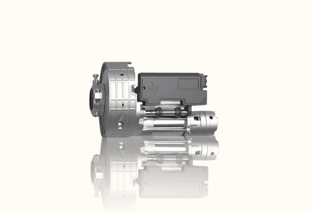
Key Components Inside a Central Drive Operator
A central drive operator is rarely “just a motor.” Below are the industrial door motor parts you’ll typically find and what each one does.
Motor (power source)
The motor supplies mechanical energy. Depending on the design, it may be AC or DC, but the core role remains: convert electrical power into rotational motion.
Gearbox / geared motor (torque multiplication)
Industrial doors frequently need torque far beyond what a motor alone can deliver directly. A gearbox / geared motor provides:
torque multiplication,
speed reduction,
and a mechanical transmission suitable for door movement.
When gearbox components wear, or when lubrication/condition is poor, you may see symptoms like increased noise, inconsistent movement, or unexpected thermal behavior.
Drive shaft / drive spindle and coupling
The drive shaft / drive spindle is where rotation is handed off into the door mechanism. A coupling / mechanical coupling connects the motor output (often via the gearbox) to the door’s turning element.
Some designs may also include a decoupling clutch or similar mechanical feature. If your system uses one, its purpose is usually to manage load transfer or allow controlled disengagement behavior. (The exact implementation varies by operator design.)
Motor brake (holding + stopping behavior)
A motor brake is commonly used to:
stop movement at end positions,
and help hold the door when the motor isn’t actively driving.
Brake behavior matters for safety and wear. If the brake engages late/early or doesn’t release smoothly, door stopping can feel inconsistent, and repeated stress can increase wear on both mechanical and electrical components.
Limit switch and/or encoder (position feedback)
Most operators need a way to know where the door is.
A limit switch is a binary position indication—essentially “at/near the limit” (open limit / close limit) used for limit control.
An encoder provides continuous or higher-resolution position feedback—used for position feedback and fine control of movement and deceleration.
Many systems rely on limit switches, encoders, or both. The choice affects how the controller performs slow-down and how accurately it can stop at the target position.
FAQ-ready distinction: limit switch vs encoder
A limit switch helps confirm end-of-travel. An encoder helps the operator control movement more precisely throughout travel.
Control board / control unit (logic + sequencing)
The control board / control unit coordinates:
open/close sequencing,
safety checks and interlocks,
speed profiles (including slow down / deceleration),
responding to limit feedback (and potentially encoder position),
and controlling outputs like contactors, brakes, and motor start/stop signals.
If the door behaves erratically—stops unexpectedly, ignores commands, or doesn’t decelerate correctly—the control board logic and sensor inputs are frequent root causes.
Contactor / reversing path (direction control)
In many industrial door operator designs, a contactor (or reversing contactor arrangement) controls motor direction and power routing for open vs close.
In plain language: contactors decide which way the motor runs, and whether it should be enabled at each step in the sequence.
Thermal overload protection and safety protection
Door motors operate under load and often cycle repeatedly. Thermal overload protection exists to protect the motor (and sometimes the control electronics) from overheating.
If thermal protection triggers, the door may:
stop mid-cycle,
refuse to run until cooled,
or behave inconsistently under heavy usage.
Overheating may be caused by mechanical drag, incorrect installation, frequent starts without duty-cycle support, poor ventilation, or failing components—so thermal trips are a symptom worth investigating, not just a resetable inconvenience.
How a Central Drive Works: The Door Motor Operation Cycle
To understand “how it works,” you need a sequence view. Here is a typical door motor operation cycle for a central drive operator.
Open command (start → accelerate → move)
The system receives an open command (from a switch, remote, BMS input, or controller interface).
The controller checks safety interlocks (for example: safety edge readiness, stop conditions not active, emergency stop not asserted).
The control outputs enable motor drive via contactor/control logic.
The motor turns the gearbox output, the drive shaft rotates, and the door mechanism moves.
If motion starts but is jerky or sounds “off,” it may indicate mechanical resistance, incorrect coupling alignment, or an electrical control issue.
Deceleration and slow-down near the end position
As the door approaches the target end position, the controller typically engages slow down / deceleration behavior:
This reduces impact forces.
It helps prevent bounce at the stop point.
It protects both the mechanism and the stopping devices.
Deceleration may be driven by:
proximity to a limit switch threshold, and/or
measured position from an encoder.
Limit stop (how the door knows it’s at the right place)
The operator ends motion when it detects it has reached the correct state:
With limit control, the limit switch triggers at the predetermined open/close end positions.
With encoder-based control, the controller can stop when the measured position reaches the programmed target.
If a door doesn’t stop at the limit, it often points to misaligned sensing hardware, wiring issues, or incorrect control settings.
Brake engagement and final holding
Once the operator reaches the stop point, it transitions from motion control to stopping/holding:
The controller commands motor brake engagement (or a stopping behavior associated with the brake system).
The door should remain stable without drifting.
Brake performance affects not just comfort, but long-term reliability. A brake that repeatedly slips or engages inconsistently can accelerate wear in mechanical and electrical components.
Close command (reverse sequence + safety checks)
A close cycle mirrors open, but safety behavior is even more critical:
The controller checks safety inputs again.
The door moves to the close end position with deceleration.
The close limit is reached, and the brake holds the door.
What happens when power is cut to a central drive operator
Exact behavior depends on the operator design and brake type, but conceptually:
If power is removed while movement is expected, the controller stops commanding motion.
If a brake is spring-applied/controlled in a particular way, it may hold the door to prevent uncontrolled motion.
Some designs may support a controlled manual release strategy.
Because “power cut behavior” is safety-critical and varies by model, treat this as a verify-by-manufacturer-spec area for your exact operator.
Safety Interlocks: The Non-Negotiable Part of Door Motor Systems
A door motor system is not just about moving the door—it’s about moving it safely.
Safety edge connection and obstacle protection
A safety edge connection typically provides a way to detect contact/obstruction and trigger a safety response, such as:
stopping movement,
reversing direction,
or preventing further closing depending on the operator’s safety logic.
When safety edges are miswired, damaged, or improperly calibrated, you may see symptoms like:
closing without obstacle protection,
nuisance stops,
or unexpected reversals.
Emergency stop and stop categories
Industrial door systems usually include an emergency stop strategy. Even if the door can receive other commands, emergency stop should dominate:
immediate inhibition of motion,
transition to safe state as defined by the safety design.
If emergency stop doesn’t behave correctly, it’s not a “small fix”—treat it as a safety audit item.
Interlocks with sensors and external safety devices
Other safety inputs can include:
photoelectric sensors,
interlocks (e.g., area occupied),
door position “okay to move” logic,
and interface checks between controller and external systems.
This is why the control board’s sensor inputs and wiring integrity matter so much.
Installation Context: Where the Motor Sits and Why It Matters
“Central” location on roller shutter / roll-up mechanisms
In many installations where you hear “central shaft motor,” the motor (or motor+gearbox assembly) is mounted so it drives a central shaft/spindle. That setup is common in roll-up styles (including a roller shutter door motor context).
A central arrangement can influence:
torque transmission path,
load distribution,
and how the operator aligns with limit sensing.
Wiring and mechanical alignment considerations (high level)
Even without going deep into wiring diagrams, these factors often affect performance:
alignment between gearbox output and coupling to the drive shaft,
secure mounting to avoid vibration,
correct routing to protect cables and avoid strain on connectors,
ensuring limit sensing hardware is positioned for repeatable detection.
When the mechanical side is correct, the electrical controller is far more likely to behave predictably.
Troubleshooting Mindset: What to Check First
When you face a door motor issue, don’t start with random swaps. Start with the system logic: command → drive enable → motion → feedback → stop/hold + safety response.
Door won’t stop at the limit
Likely categories:
limit switch misalignment or failure,
incorrect limit switch wiring or configuration in the control unit,
controller logic/parameters incorrect,
mechanical binding causing the door to overshoot expected behavior.
Door stops too early (position feedback mismatch)
Possibilities:
limit switch triggered sooner than expected,
encoder feedback miscalibrated (if used),
deceleration/stop thresholds set incorrectly in the control unit,
mechanical load causing the system to behave differently than expected.
Door won’t move (power/control path)
This usually points to:
lack of power to the control board/motor circuit,
contactor not engaging,
safety interlock not satisfied (safety edge, emergency stop, sensor chain),
thermal protection active.
Noise, vibration, and uneven movement (mechanical vs control)
Noise causes often have two “buckets”:
Mechanical transmission issues (gearbox, coupling alignment, drive shaft load)
Electrical/control behavior (contactor issues, inconsistent enable/stop timing)
Because the symptoms overlap, you typically confirm mechanical condition before assuming a control-board fault.
Overheating: when thermal protection triggers
If you see thermal trips:
investigate mechanical drag first (door not moving freely),
confirm duty-cycle expectations for your usage pattern,
check airflow/ventilation if the motor or control enclosure is sensitive,
and inspect for failing components in the gearbox/brake area.
Choosing a Central Motor for Industrial Doors (What to Confirm)
Even if you already know “central motor” is the right category, you still need to confirm the details that affect safe, reliable operation.
Confirm door type and movement mechanism
A central drive might be used for:
industrial rolling door operator designs,
roll-up/rolling styles (often described as roller shutter door motor contexts),
and other operator types depending on the door mechanism.
If the mechanism differs, transmission and sensing strategies can differ too.
Confirm operating cycle and duty considerations
Central motors and door motor systems are designed for certain usage patterns (how often they open/close, under what load). If usage exceeds intended duty, overheating and wear accelerate.
Confirm feedback type (limit switch vs encoder)
If your application needs precise stopping, consistent positioning, or specialized speed profiles, confirm whether the operator’s limit control approach (limit switch, encoder, or both) matches your needs.
Confirm brake and safety edge strategy
The braking system and safety edge connection strategy must match your operational risk profile. A brake that holds reliably and a safety edge chain that responds correctly are foundational for safe door movement.
FAQ
1) What is a central motor for industrial doors?
A central motor for industrial doors is the power drive unit in a door operator system that turns a central drive shaft/spindle to move the door, using a controller for speed, stopping, and safety interlocks.
2) What parts are in a central drive operator?
Common door operator components include a motor, gearbox / geared motor, drive shaft with coupling, motor brake, limit switch and/or encoder for position feedback, a control board, and safety protection like thermal overload protection.
3) How does a central drive motor work?
It follows a command-and-feedback cycle: the controller enables motor drive, the door moves with an open/close sequence, the controller uses limit/encoder feedback to stop accurately (often with deceleration), and the brake engages to hold the door while safety interlocks monitor conditions.
4) Limit switch vs encoder for door motors—what’s the difference?
A limit switch typically signals that the door has reached (or is near) the end position. An encoder provides more detailed position feedback, enabling more precise stopping and smoother deceleration control.
5) What does the motor brake do in a door operator?
The motor brake helps stop motion and hold the door at end positions, reducing drift and impact forces. Brake timing and reliability affect both safety and component wear.
6) What should I check if a central door motor overheats?
Start with mechanical load issues (binding, misalignment), confirm usage/duty expectations, verify installation and ventilation, and inspect for components that could increase friction or electrical stress. Also check whether thermal overload protection is the actual trigger.
Conclusion
A central motor for industrial doors is best understood as a coordinated electromechanical drive system—not just a motor. It includes the powertrain (motor + gearbox + drive shaft/coupling), stopping hardware (motor brake), sensing (limit control via limit switch and/or position feedback via encoder), and the intelligence (control board). Together, these manage a predictable door motor operation cycle: open/close sequence, deceleration, limit stop, and safe holding—while safety interlocks (including a safety edge connection and emergency stop logic) reduce risk.
If you’re selecting or maintaining a central drive operator, use the checklist in your head: power path + feedback path + safety path + stopping/braking path. That approach makes troubleshooting faster and makes specification decisions far less guesswork.
Other Blogs


