Blog
How to Install a Barrier Gate: Foundation, Wiring, Boom Arm and Testing
Author
Ray
Published
Category
Car Park Barriers
Learn how to install a barrier gate step by step, including foundation preparation, cabinet mounting, boom arm installation, wiring, safety sensors, adjustment, and testing.

Author
Ray
An experienced automation specialist with a strong background in motor technology and industrial solutions. With years of expertise in central motors, tubular motors, and automation systems, the author is dedicated to sharing insights that connect engineering innovation with real-world applications. Passionate about advancing reliable, energy-efficient, and high-performance automation products for global markets.
What’s better than insider perks, pro tips, and surprises?
Sign up to get the most recent blog articles in your email every week.
Join now.
WHY I WRITE THIS
About my business
Our company’s main product lines include tubular motors, sliding gate motors, swing gate motors, roller shutter motors, and other door automation solutions, all manufactured by trusted partner factories we have worked with for many years.
Our Services
I help them with sales and export operations, while our company also provides sourcing and procurement services in China to help international clients solve supply-related challenges. If you need assistance with procurement, please feel free to contact us.
Installing a barrier gate requires more than securing a cabinet to the ground and connecting a power supply. A reliable automatic barrier gate system depends on correct site preparation, mechanical installation, electrical wiring, safety devices, boom arm adjustment, and final commissioning.
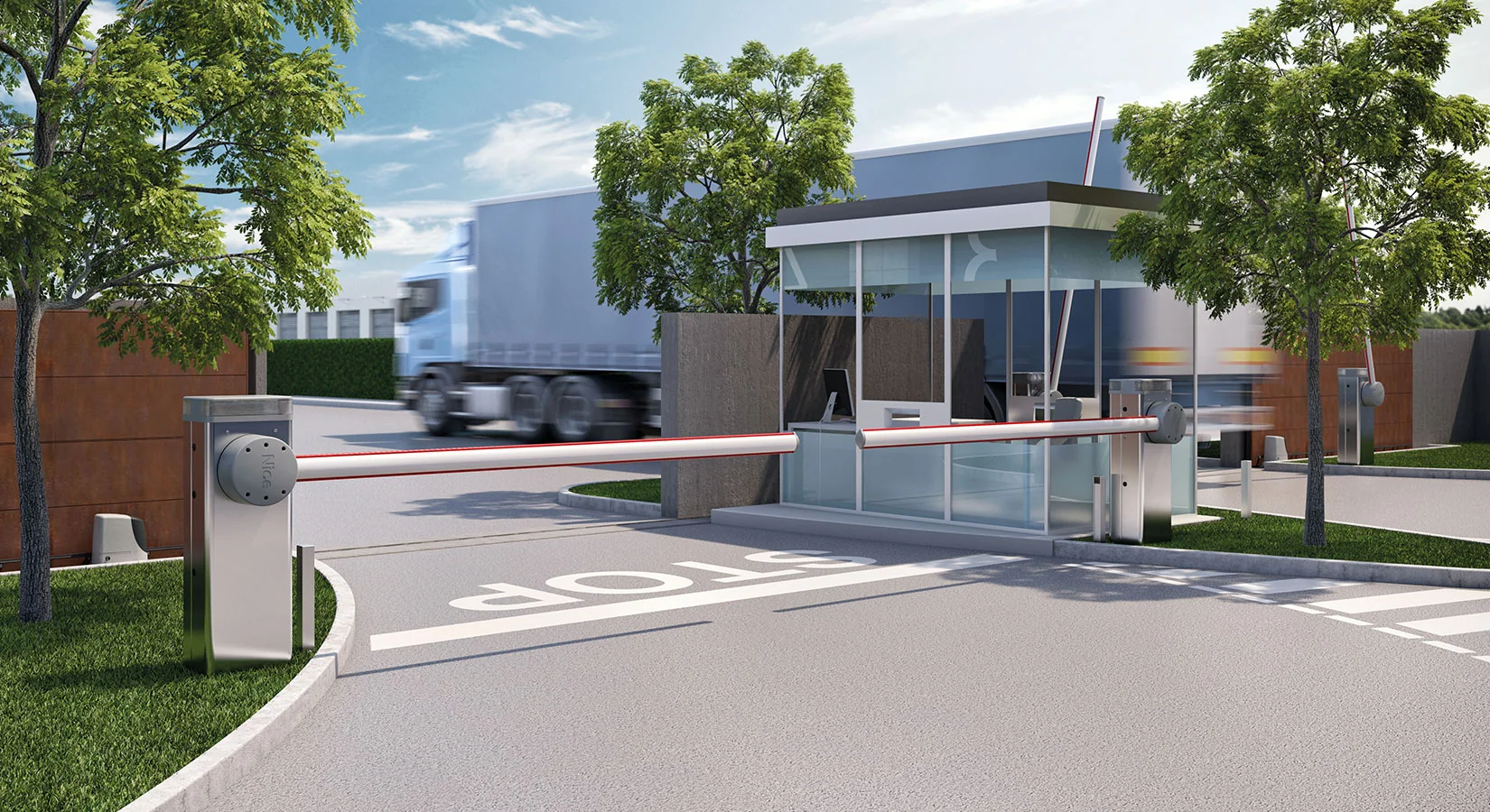
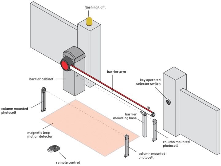
A typical barrier gate installation includes the operator cabinet, boom arm, control board, power supply, access-control equipment, vehicle detection devices, and safety sensors. Depending on the application, the system may also integrate photocells, inductive loop detectors, radar sensors, traffic lights, license plate recognition cameras, or other access-control equipment. Modern barrier gate products are available with different boom configurations, including straight, folding, telescopic, and fence-style arms.
The exact installation procedure varies by manufacturer and model. Therefore, the product-specific installation manual and wiring diagram should always take precedence over a general guide. The following process provides a practical framework for installing an automatic barrier gate correctly.
What Do You Need Before Installing a Barrier Gate?
Before beginning the installation, confirm that the barrier gate is suitable for the entrance, traffic conditions, boom length, operating frequency, and required access-control functions.
Main Barrier Gate Components
A typical automatic barrier gate system may include:
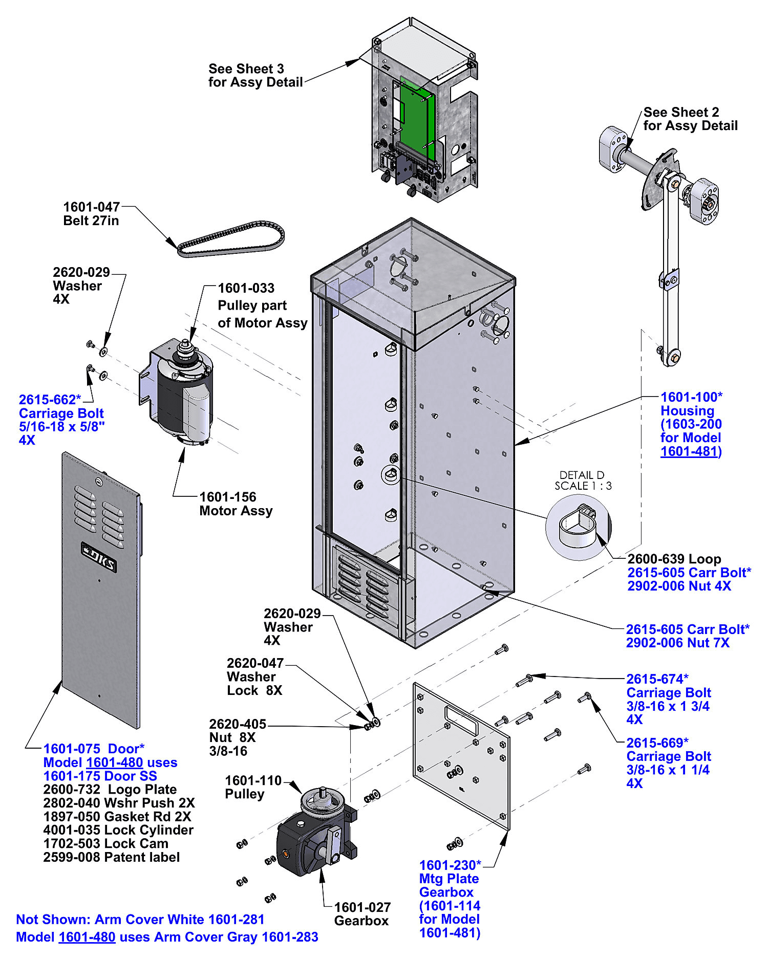
Barrier gate operator cabinet
Motor and transmission mechanism
Control board
Boom arm
Boom arm mounting bracket
Counterbalance or spring mechanism
Manual release mechanism
Power cables
Control cables
Photocells or photo beams
Inductive loop detector
Radar or vehicle detector
Access-control reader
License plate recognition camera
Traffic signal light
Warning signs or lights
Not every installation requires all of these components. For example, a simple private parking entrance may use a remote control, while a commercial parking facility may integrate a barrier gate with a loop detector, access-control reader, and license plate recognition system.
Check the Barrier Gate Specifications
Before installation, verify the specifications of the selected model, particularly:
Maximum recommended boom length
Boom type
Power supply
Motor rating
Opening and closing speed
Operating temperature
Protection rating
Mounting requirements
Safety-device compatibility
Control input and output configuration
For example, current barrier gate products from ZKTeco include straight, folding, and fence boom configurations with different supported boom lengths and power requirements.
How to Choose the Installation Location
The installation location directly affects the safety and reliability of the barrier gate.
Check the Traffic Lane
Measure the entrance width before selecting the barrier gate and boom arm. The boom should cover the required vehicle lane without creating unnecessary obstruction.
Consider:
Lane width
Vehicle approach direction
Vehicle turning radius
Position of the driver's window
Pedestrian movement
Adjacent lanes
Distance from walls and other equipment
The barrier gate should have enough space for the boom to move through its complete opening and closing range. Manufacturer documentation also recommends installing the operator on a firm, level surface and maintaining adequate clearance around the moving boom.
Check the Ground Condition
The operator should be installed on a stable and level surface. If the existing ground cannot provide adequate support, a concrete foundation may be required.
An uneven or unstable foundation can cause:
Cabinet movement
Mechanical vibration
Boom misalignment
Increased motor load
Loose anchor bolts
Long-term operating problems
The foundation dimensions and anchoring method should be determined according to the specific barrier gate model rather than using one universal size. Some manufacturer manuals specify that the concrete foundation should extend beyond the footprint of the operator.
Plan Cable Routes Before Installation
Power and control wiring should be planned before the concrete work is completed.
Cable conduits should provide a protected route between the barrier gate, control equipment, and other peripheral devices. Manufacturer documentation commonly recommends separating power cables from control cables by using different conduits.
This approach can help reduce electrical interference and makes future maintenance easier.
How to Prepare the Barrier Gate Foundation
A solid foundation is one of the most important parts of a permanent barrier gate installation.
Mark the Installation Position
Start by marking:
The centerline of the traffic lane.
The position of the barrier cabinet.
The direction of the boom arm.
The location of anchor bolts.
The cable-entry position.
The position of the optional support post.
Make sure the boom arm will not strike walls, signs, vehicles, lighting poles, or other structures during operation.
Install Cable Conduits
Before pouring or finishing the foundation, install the required cable conduits.
Separate routes may be required for:
AC power
Low-voltage control signals
Loop detector wiring
Photocell wiring
Access-control communication
Other peripheral devices
The conduit layout should follow local electrical requirements and the manufacturer's instructions.
Construct a Level Concrete Foundation
If a concrete foundation is required, it should be:
Strong enough to support the operator
Level
Properly positioned
Suitable for the anchor system
Large enough for the specified mounting points
Allow the concrete to reach the required strength before loading it with the barrier gate.
The foundation should not simply be judged by whether the cabinet can physically stand on it. It must provide sufficient structural stability for repeated opening and closing cycles.
How to Mount the Barrier Gate Cabinet
Once the foundation is ready, the operator cabinet can be positioned and anchored.
Position the Operator
Place the cabinet according to the previously marked mounting position.
Check:
Cabinet orientation
Boom direction
Vertical alignment
Cable-entry location
Maintenance access
Clearance from nearby structures
Some manufacturer instructions specify that the operator should remain very close to perpendicular to the horizontal installation surface.
Drill and Install the Anchors
Mark the mounting holes through the cabinet base or mounting plate.
Then:
Remove the cabinet if necessary.
Drill the specified anchor holes.
Clean the holes.
Install the appropriate anchors.
Position the cabinet again.
Tighten the mounting hardware.
Check alignment.
Do not overtighten or use an anchor system that is incompatible with the foundation material.
Confirm Maintenance Access
Leave sufficient space to open the cabinet and access:
Control board
Motor
Wiring terminals
Fuses or breakers
Manual release mechanism
Adjustment components
A barrier gate that is difficult to service can increase maintenance time and operating costs.
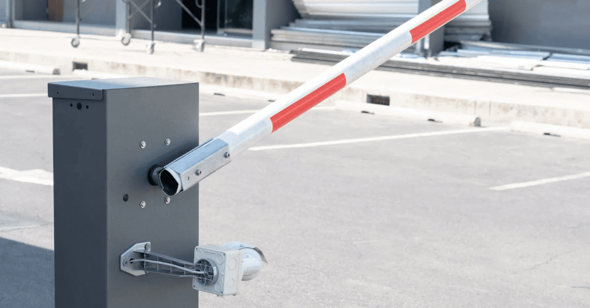
How to Install the Barrier Gate Boom Arm
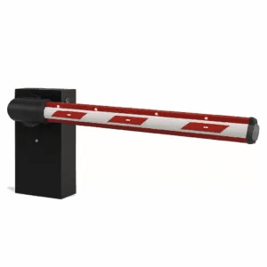
The boom arm is the most visible moving component of the system and must be installed according to the operator manufacturer's instructions.
Select the Correct Boom Arm
Boom arms are available in several configurations, including:
Straight boom
Folding boom
Telescopic boom
Fence boom
Anti-collision boom
The correct boom type depends on the installation environment and required lane coverage. Current commercial barrier gate systems can support different boom configurations and lengths depending on the model.
Attach the Boom Arm to the Bracket
Position the boom arm on the operator's mounting bracket.
Align the mounting holes and install the specified fasteners, washers, and nuts. Tighten the hardware according to the manufacturer's procedure.
Do not modify the boom arm length or mounting structure unless the manufacturer specifically permits it. Some manufacturer documentation warns that incorrect boom modification can damage the barrier mechanism.
Check Boom Alignment
After installation, manually check the boom movement if the manufacturer's procedure allows it.
The boom should:
Move smoothly
Remain properly aligned
Reach the specified open position
Reach the specified closed position
Avoid contact with surrounding structures
If the system uses a support post, confirm that the boom reaches the support correctly when fully closed.
How to Balance and Adjust the Boom Arm
The boom arm places a mechanical load on the operator. Counterbalance springs or other balancing mechanisms are therefore important in many barrier gate designs.
Why Boom Balance Matters
Incorrect balancing can contribute to:
Excessive motor load
Slow movement
Unstable movement
Increased mechanical wear
Difficulty reaching the correct open or closed position
The balancing procedure varies significantly between models.
Adjust the Counterbalance According to the Manual
Do not use a generic spring tension value for every barrier gate.
The required adjustment depends on factors such as:
Boom length
Boom weight
Boom configuration
Operator mechanism
Spring specification
If the boom arm is replaced with a different length or type, the balance may need to be recalibrated according to the manufacturer's procedure.
How to Wire a Barrier Gate
Electrical installation should be performed with the power disconnected and according to the wiring diagram supplied with the specific operator.
Disconnect Power Before Wiring
Always isolate the electrical supply before opening the operator cabinet or connecting wires.
Manufacturer installation documentation explicitly instructs installers to cut off power before installation and to connect power and control wiring according to the control-board wiring diagram.
Connect the Power Supply
The power connection must match the specifications of the barrier gate.
Depending on the product, the system may use AC or DC power. For example, ZKTeco's current ProBG3000 series specifies 24 V DC and 100–240 V AC options, while other models use different configurations.
Therefore, never assume that two barrier gates use the same supply voltage simply because they have similar mechanical designs.
Connect Control Wiring
Control wiring may include connections for:
Open command
Close command
Stop command
Access-control input
Vehicle detector
Photocell
Radar
Traffic light
Alarm
Communication equipment
The exact terminals and signal logic depend on the controller.
Separate Power and Control Cables
Where possible, route power and low-voltage control cables through separate conduits.
This is recommended in manufacturer installation documentation and can simplify troubleshooting while reducing the risk of electrical interference.
How to Install Photocells and Safety Sensors
A barrier gate should not be treated as a simple motorized arm. The safety system is an essential part of the installation.
Photocell Installation
Photocells use a transmitter and receiver to create a monitored detection path.
When an object interrupts the beam, the control system can prevent the boom from closing or trigger the appropriate reversal/safety response, depending on the system design.
The photocell should be:
Installed at the correct height
Properly aligned
Protected from accidental damage
Connected to the correct safety input
Tested after installation
Safety requirements vary by jurisdiction and equipment. For example, DoorKing identifies monitored non-contact photo beams and contact safety devices as entrapment-protection solutions for applicable automatic gate systems.
Loop Detector Installation
An inductive loop detector can detect vehicles in the entrance or exit lane.
The loop is typically installed in or beneath the road surface and connected to a vehicle detector.
Depending on the system design, loop detection can be used to:
Detect vehicle presence
Prevent premature closing
Trigger opening
Keep the barrier open while a vehicle is detected
Reduce the risk of the boom closing onto a vehicle
Barrier gate manufacturers commonly provide dedicated connections for vehicle detectors and loop sensors.
Radar and Other Vehicle Detection
Radar-based vehicle detection can be used where loop installation is undesirable or where additional detection coverage is required.
Some barrier gate systems support radar, infrared detectors, and loop detectors as anti-smash or automatic-closing inputs.
The choice should be based on traffic conditions, road construction, detection requirements, and the control system.
How to Connect an Access Control System
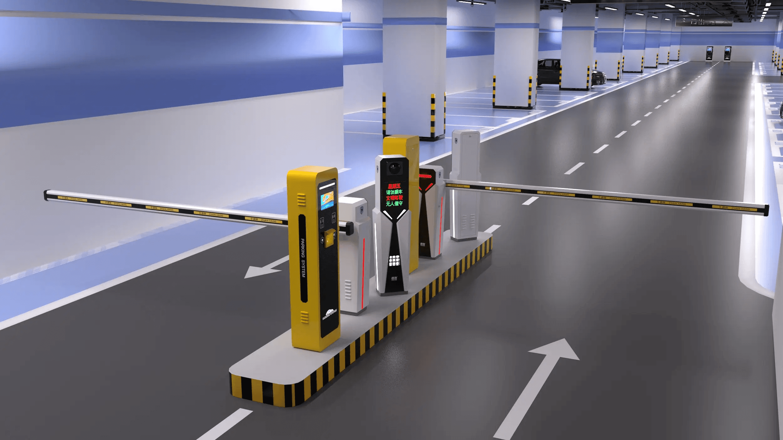
Barrier gates are often part of a larger vehicle access-control system.
Common Access Methods
A barrier gate can be integrated with:
Remote controls
RFID readers
Keypads
QR-code systems
License plate recognition cameras
Intercom systems
Parking management systems
Building access-control systems
The access-control device normally sends an open command to the barrier controller.
The barrier itself should still retain the required safety functions independently of the access-control system.
Integrate License Plate Recognition
For automated parking entrances, a license plate recognition camera can identify an authorized vehicle and send an opening command to the barrier gate controller.
The physical installation should consider:
Camera position
Vehicle stopping point
Recognition distance
Lighting
Boom position
Network connection
Controller interface
Modern barrier gate systems may provide dedicated interfaces for access cameras and other traffic-management devices.
How to Adjust the Barrier Gate Open and Close Positions
After the mechanical and electrical installation is complete, the operator must be configured for the correct operating positions.
Set the Open Position
The open position should provide sufficient clearance for vehicles while keeping the boom within its intended mechanical range.
Check that:
The boom reaches the specified open position.
The motor does not continue forcing the mechanism after reaching the limit.
The boom does not contact nearby structures.
The position is stable over repeated cycles.
Set the Closed Position
When closed, the boom should cover the intended lane without creating unnecessary mechanical stress.
Check:
Boom alignment
Support-post contact
Closed-angle setting
Limit position
Vehicle clearance
Safety-device operation
Some modern controllers provide dedicated parameters for open and close positions, open and close angles, speed, slow-down points, loop-sensor behavior, and automatic closing.

How to Test a Barrier Gate After Installation
Testing should be performed systematically rather than simply opening and closing the boom once.
Mechanical Inspection
Before powering the system, check:
Cabinet anchors
Boom mounting bolts
Support bracket
Spring or counterbalance
Manual release
Cable glands
Conduit entries
Mechanical clearance
No component should interfere with the movement of the boom.
Electrical Inspection
Check:
Power supply
Grounding
Terminal connections
Control inputs
Safety inputs
Sensor connections
Communication connections
Confirm that all connections match the manufacturer's wiring diagram.
Functional Testing
Perform several complete operating cycles.
Test:
Open command.
Full opening.
Stop command if supported.
Close command.
Full closing.
Automatic closing if enabled.
Photocell interruption.
Vehicle detection.
Access-control activation.
Manual release.
The objective is to verify not only that the motor operates, but that the complete system responds correctly to normal and abnormal conditions.
Safety Testing
Safety devices should be tested individually.
For example, interrupt the photocell beam during the appropriate stage of operation and verify the response specified by the equipment manufacturer.
Similarly, test the vehicle detector and confirm that the barrier responds correctly when a vehicle remains within the detection zone.
Do not consider the installation complete until the safety functions have been verified.
Common Barrier Gate Installation Mistakes
Installing the Operator on an Unstable Foundation
A weak or uneven foundation can cause cabinet movement and alignment problems.
Choosing the Wrong Boom Length
A boom that is too short may not cover the lane correctly. A boom that is too long or too heavy for the operator can exceed the manufacturer's mechanical specifications.
Incorrect Spring Adjustment
An incorrectly balanced boom can increase mechanical and motor loads.
Mixing Power and Control Wiring
Routing high-voltage power and low-voltage signal wiring without following the manufacturer's recommendations can complicate installation and troubleshooting.
Incorrect Photocell Alignment
Even a correctly wired photocell may fail to provide reliable protection if the transmitter and receiver are not aligned properly.
Installing the Loop Detector Incorrectly
The loop position, dimensions, cable routing, and detector configuration must match the intended vehicle-detection application.
Testing Without Safety Devices
A barrier should not be commissioned as a complete automatic system simply because the boom opens and closes.
Safety devices and vehicle detection functions must also be tested.
Ignoring Maintenance Access
The cabinet should remain accessible for future inspection, wiring changes, component replacement, and controller adjustment.
Barrier Gate Installation Checklist
Before handing over the system, use the following checklist:
Installation Item | Check |
|---|---|
Installation location | Suitable for vehicle traffic |
Foundation | Level and structurally stable |
Cable conduits | Installed and protected |
Operator cabinet | Firmly anchored |
Boom arm | Correct type and length |
Boom mounting | Secure and aligned |
Counterbalance | Adjusted according to manufacturer procedure |
Power wiring | Correctly connected |
Control wiring | Correctly connected |
Photocells | Installed and tested |
Loop detector | Installed and tested where required |
Radar/vehicle detector | Tested where applicable |
Access control | Tested |
Open position | Correctly adjusted |
Close position | Correctly adjusted |
Manual release | Tested |
Safety functions | Tested |
Complete operating cycles | Verified |
Barrier Gate Installation FAQ
How long does it take to install a barrier gate?
Installation time depends on the site conditions, foundation requirements, wiring distance, boom configuration, and number of peripheral devices. A straightforward replacement installation can be much faster than a new installation requiring concrete work, underground conduits, loop detectors, and access-control integration.
Does a barrier gate need a concrete foundation?
Not every model requires the same foundation arrangement. Some operators can be installed on an existing suitable surface, while others require a dedicated concrete base. The foundation should meet the manufacturer's mounting and structural requirements.
What wiring is required for a barrier gate?
The exact wiring depends on the operator and application. A typical installation may require power wiring, control wiring, safety-device wiring, vehicle-detector wiring, and connections to access-control equipment. Always use the wiring diagram for the specific controller.
How do you install a barrier gate boom arm?
The boom arm is mounted to the operator's dedicated bracket using the specified hardware. After installation, the boom must be checked for alignment, mechanical clearance, balance, and correct open and closed positions. Some manufacturers recommend professional assistance when changing boom configurations.
What safety devices are used with barrier gates?
Common devices include photocells, photo beams, inductive loop detectors, radar sensors, reversing edges, and other vehicle or obstacle detection systems. The required devices depend on the barrier design, installation environment, applicable safety requirements, and control system.
Why does a barrier gate fail to close completely?
Possible causes include incorrect limit settings, mechanical obstruction, incorrect boom balance, sensor input, control-board settings, or a problem with the motor or transmission mechanism. Check the mechanical installation and controller settings before replacing components.
Final Considerations for Barrier Gate Installation
A successful barrier gate installation combines mechanical stability, correct electrical installation, reliable vehicle detection, effective safety protection, and proper commissioning.
The process should begin with site assessment and foundation preparation rather than with the motor itself. Once the cabinet is securely installed, the boom arm can be mounted and balanced, followed by power and control wiring. Safety devices such as photocells and vehicle detectors should then be connected and tested before the system is placed into normal service.
Most importantly, barrier gates are not universal systems. Boom length, power supply, foundation dimensions, controller terminals, limit settings, spring adjustment, and safety-device requirements vary between models. The installation manual supplied with the specific barrier gate should therefore remain the primary technical reference throughout installation and commissioning.
Other Blogs